йҖҸи§ҶжҠ•еҪұзҹ©йҳө
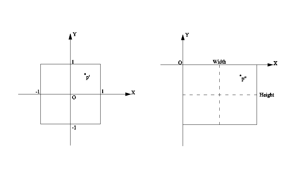
жҠ•еҪұе°ұжҳҜе°ҶдёҖдёӘдёүз»ҙз©әй—ҙдёӯжҹҗзӮ№пјҲжҲ–зәҝгҖҒйқўзӯүпјүж №жҚ®дёҖе®ҡзҡ„规еҲҷиҪ¬жҚўеҲ°дәҢз»ҙз©әй—ҙдёӯпјҢжҠ•еҪұж №жҚ®е…¶жҠ•еҪұж–№ејҸеҸҲеҲҶдёәйҖҸи§ҶжҠ•еҪұе’ҢжӯЈе°„жҠ•еҪұпјҢеҰӮдёӢеӣҫеҚідёәйҖҸи§ҶжҠ•еҪұзҡ„зӨәж„Ҹеӣҫпјҡ

йҖҸи§ҶжҠ•еҪұжңүеӣӣдёӘйҮҚиҰҒзҡ„еҸӮж•°пјҢеҚіи§Ҷи§’(ПҶ)гҖҒе®Ҫй«ҳжҜ”(Width/Height)гҖҒиҝ‘е№ійқў(ZNearPlane)е’Ңиҝңе№ійқў(ZFarPlane)пјҢжүҖд»ҘеңЁж‘„еғҸжңәдёӯиғҪзңӢеҲ°зҡ„еҢәеҹҹе°ұжҳҜи§Ҷи§’иҢғеӣҙеҶ…гҖҒиҝ‘е№ійқўеҲ°иҝңе№ійқўд№Ӣй—ҙзҡ„иҢғеӣҙгҖӮеҜ№дәҺдё–з•Ңз©әй—ҙдёӯд»»ж„ҸдёҖзӮ№жҲ–еҗ‘йҮҸPпјҢиҰҒе°Ҷе…¶жҠ•еҪұеҲ°еұҸ幕дёҠжҳҫзӨәпјҢйҰ–е…ҲиҰҒе°Ҷеҗ‘йҮҸпјҲOиЎЁзӨәдё–з•Ңз©әй—ҙзҡ„еқҗж ҮеҺҹзӮ№пјүиҪ¬жҚўеҲ°ж‘„еғҸжңәз©әй—ҙпјҢеҚіеҗ‘йҮҸпјҲCиЎЁзӨәж‘„еғҸжңәз©әй—ҙзҡ„еқҗж ҮеҺҹзӮ№пјүпјҢе…¶иҪ¬жҚўе…¬ејҸеҰӮдёӢпјҡ

еңЁжӯӨпјҢж‘„еғҸжңәзҹ©йҳөCameraMatrixеҚіж‘„еғҸжңәи§Ҷеӣҫзҹ©йҳөгҖӮеңЁеҫ—еҲ°ж‘„еғҸжңәз©әй—ҙдёӯPзӮ№зҡ„еҗ‘йҮҸеҗҺпјҢ然еҗҺж №жҚ®ж‘„еғҸжңәжҠ•еҪұзӣёе…іеҸӮж•°е°ҶиҜҘзӮ№PжҠ•еҪұеҲ°еұҸ幕дёҠпјҢеҰӮдёӢеӣҫжүҖзӨәпјҡ

з”ұдёҠеӣҫеҸҜзҹҘпјҡ
ж‘„еғҸжңәеқҗж ҮеҺҹзӮ№иҮіеұҸ幕зҡ„и®Ўз®—и·қзҰ»дёәпјҡ

еҲҷPзӮ№еңЁеҚ•дҪҚе№ійқўдёҠзҡ„жҠ•еҪұдҪҚзҪ®дёәпјҡ


жңҖеҗҺе°ҶеҚ•дҪҚе№ійқўдёҠзҡ„жҠ•еҪұдҪҚзҪ®иҪ¬жҚўеҲ°еұҸ幕平йқўдёҠпјҢеҰӮдёӢеӣҫжүҖзӨәпјҡ
жүҖд»ҘеңЁеұҸ幕平йқўдёҠзҡ„жҠ•еҪұеқҗж Үдёәпјҡ

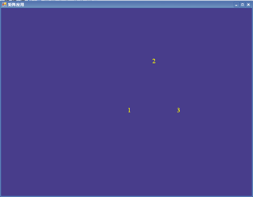
еҰӮдёӢд»Јз Ғз»ҳеҲ¶дёүдёӘз©әй—ҙеҗ‘йҮҸеҲ°еұҸ幕дёҠзҡ„жҠ•еҪұпјҡ
Vector4 calV1 = new Vector4(0f,0f,0f,1f);
calV1 =Vector4.Transform(calV1, viewMatrixComp);
int x1 = (int)(((float)calV1.X*this.Height/(float)(2 * calV1.Z * Math.Tan((float)Math.PI / 4))) + this.Width / 2);
int y1 = (int)(-calV1.Y * (float)this.Height / (2 * calV1.Z * Math.Tan((float)Math.PI / 4)) + this.Height / 2);
myFont.DrawText(sprite, "1", x1, y1, Color.Yellow);
Vector4 calV2 = new Vector4(5f, 10f, 0, 1);
calV2 = Vector4.Transform(calV2, viewMatrixComp);
int x2 = (int)(((float)calV2.X * this.Height / (float)(2 * calV2.Z * Math.Tan((float)Math.PI / 4))) + this.Width / 2);
int y2 = -(int)(calV2.Y * (float)this.Height / (2 * calV2.Z * Math.Tan((float)Math.PI / 4))) + this.Height / 2;
myFont.DrawText(sprite, "2", x2, y2, Color.Yellow);
Vector4 calV3 = new Vector4(10f, 0f, 0, 1);
calV3 = Vector4.Transform(calV3, viewMatrixComp);
int x3 = (int)(((float)calV3.X * this.Height / (float)(2 * calV3.Z * Math.Tan((float)Math.PI / 4))) + this.Width / 2);
int y3 = (int)(-calV3.Y * (float)this.Height / (2 * calV3.Z * Math.Tan((float)Math.PI / 4)) + this.Height / 2);
myFont.DrawText(sprite, "3", x3, y3, Color.Yellow);
е…¶з»“жһңеҰӮдёӢеӣҫжүҖзӨәпјҡ
еңЁDirectXдёӯжҸҗдҫӣдәҶеҲӣе»әжҠ•еҪұзҹ©йҳөзҡ„ж–№жі•пјҢеҰӮMatrix.PerspectiveFovLH()гҖҒMatrix.PerspectiveFovRH()гҖҒMatrix.PerspectiveLH()гҖҒMatrix.PerspectiveRH()гҖҒMatrix.PerspectiveOffCenterLH()е’ҢMatrix.PerspectiveOffCenterRH()гҖӮдёӢйқўдё»иҰҒд»Ӣз»ҚMatrix.PerspectiveFovLH()ж–№жі•пјҢе…¶е®ҡд№үеҰӮдёӢпјҡ
public staticMatrix PerspectiveFovLH(float fieldOfViewY,float aspectRatio,float znearPlane,float zfarPlane);
е…¶дёӯеҸӮж•°fieldOfViewYиЎЁзӨәеһӮзӣҙYиҪҙе№ійқўпјҲеҚіXZе№ійқўпјүдёҠзҡ„и§Ҷи§’пјҢеҸӮж•°aspectRatioиЎЁзӨәеұҸ幕е®Ҫй«ҳжҜ”пјҢеҸӮж•°znearPlaneиЎЁзӨәж‘„еғҸжңәеҸҜи§Ғзҡ„жңҖе°Ҹи·қзҰ»пјҢеҸӮж•°zfarPlaneиЎЁзӨәж‘„еғҸжңәеҸҜи§Ғзҡ„жңҖиҝңи·қзҰ»гҖӮеҰӮжһңз”ЁhиЎЁзӨәи§ҶеӣҫеұҸ幕й«ҳеәҰпјҢеҲҷh=cot(fieldofViewY/2)пјҲжӯӨеӨ„и®Ўз®—зҡ„дёәзӣёеҜ№дәҺзңҹе®һеұҸ幕е°әеҜёзҡ„жҜ”дҫӢпјүпјӣи§ҶеӣҫеұҸ幕е®ҪеәҰз”ЁwиЎЁзӨәпјҢеҲҷw=hГ—aspectRatioпјҢеҲҷз”ҹжҲҗзҡ„жҠ•еҪұзҹ©йҳөеҗ„еҸӮж•°дёәпјҡ

еҰӮдёӢд»Јз Ғз”ҹжҲҗзҡ„дёҖдёӘжҠ•еҪұзҹ©йҳөпјҡ
Matrix projMatrix = Matrix.PerspectiveFovLH((float)Math.PI / 2, this.Width / this.Height, 1.0f, 1000.0f);
device.Transform.Projection = projMatrix;
жүҖд»ҘеҜ№дәҺдёҖдёӘдё–з•Ңеқҗж Үзі»дёӯзҡ„еҗ‘йҮҸVectorOPпјҢйңҖиҰҒе…Ҳз»ҸиҝҮж‘„еғҸжңәз©әй—ҙеқҗж ҮиҪ¬жҚўпјҢ然еҗҺз»ҸиҝҮжҠ•еҪұзҹ©йҳөеҸҳжҚўпјҢжңҖеҗҺд№ҳд»ҘеұҸ幕зҹ©йҳөжүҚеҫ—еҲ°е…¶еңЁеұҸ幕дёҠзҡ„еқҗж ҮдҪҚзҪ®пјҢеҰӮдёӢе…¬ејҸпјҲеңЁжӯӨеҗ‘йҮҸйғҪдёәеӣӣз»ҙеҗ‘йҮҸгҖҒзҹ©йҳөдёәеӣӣйҳ¶зҹ©йҳөпјүпјҡ
VectorOPP=VectorOP*viewMatrix*projectionMatrix*ScaleMatrix*ScreenMatrix
е…¶дёӯScreenMatrixзҹ©йҳөдёәеұҸ幕еҸҳжҚўзҹ©йҳөпјҢе…¶еҗ„е…ғзҙ еҖјдёәпјҡ

ScaleMatrixзҹ©йҳөдёәзј©ж”ҫзҹ©йҳөпјҢиҜҘзҹ©йҳөдёӯзј©ж”ҫеӣ еӯҗйғҪдёҖж ·пјҢе…¶еҖјдёәеҗ‘йҮҸVectorOPвҖҷ=VectorOP*viewMatrix*projectionMatrixдёӯжңҖеҗҺдёҖдёӘеҖјпјҢеҰӮпјҡ

еҰӮдёӢйҖҡиҝҮдёҠйқўе…¬ејҸи®Ўз®—жҠ•еҪұиҮіе№ійқўдҪҚзҪ®зҡ„д»Јз Ғпјҡ
Vector4 VectorOP = new Vector4(5f, 10f, 0f, 1f);
VectorOP = Vector4.Transform(VectorOP, viewMatrixComp);
VectorOP = Vector4.Transform(VectorOP, projMatrix);
Matrix ScreenMatrix = Matrix.Zero;
ScreenMatrix.M11 = ScreenMatrix.M41= (float)this.Width / 2; ScreenMatrix.M22 = -(float)this.Height / 2;
ScreenMatrix.M42 = (float)this.Height / 2;
VectorOP = Vector4.Multiply(VectorOP, 1.0f / VectorOP.W);
VectorOP = Vector4.Transform(VectorOP, ScreenMatrix);
myFont.DrawText(sprite, "+", (int)VectorOP.X, (int)VectorOP.Y, Color.Yellow);
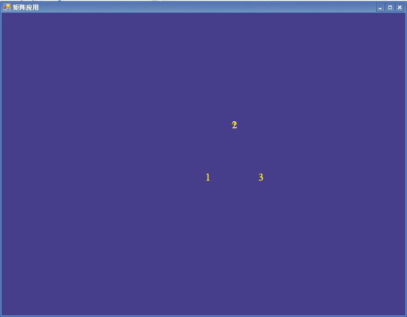
иҝҗиЎҢзЁӢеәҸпјҢз”ұдәҺи®ҫзҪ®жҳҫзӨәеҗ‘йҮҸдёҺеүҚйқўе®ҡд№ү第дәҢдёӘеҗ‘йҮҸзҡ„еҖјдёҖж ·пјҢжүҖд»ҘеңЁжӯӨжҳҫзӨәзҡ„дҪҚзҪ®дёҺеүҚйқўжҳҫзӨәдҪҚзҪ®зӣёеҗҢпјҢеҰӮдёӢеӣҫжүҖзӨәпјҡ
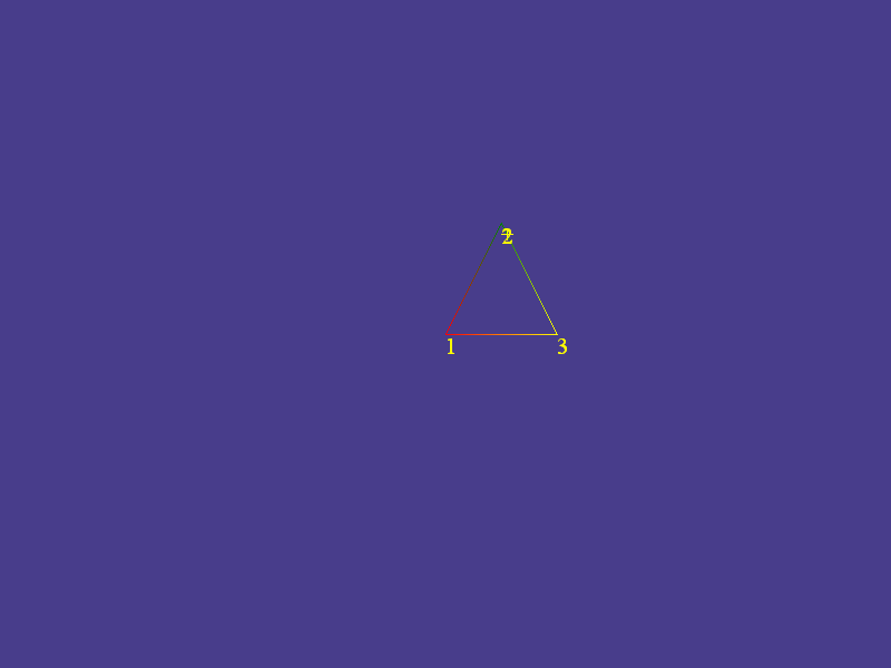
зҺ°еңЁж №жҚ®еүҚйқўдёүдёӘеҗ‘йҮҸдҪҚзҪ®жқҘз»ҳеҲ¶дёҖдёӘдёүи§’еҪўжқҘе’ҢеүҚйқўиҮӘе®ҡд№үзҡ„з®—жі•жқҘиҝӣиЎҢжҜ”иҫғпјҢеҰӮдёӢд»Јз ҒпјҲиҜҘж®өд»Јз Ғд№ҹдҪҚдәҺRender()еҮҪж•°дёӯпјүпјҡ
Vector3 cameraPosition = new Vector3(0, 0, -30);
Vector3 cameraTarget = new Vector3(0f, 0.0f, 0.0f);
Vector3 cameraUpVector = new Vector3(0, 1, 0);
Matrix viewMatrixComp = Matrix.LookAtLH(cameraPosition, cameraTarget, cameraUpVector);
device.Transform.View = viewMatrixComp;
Matrix projMatrix = Matrix.PerspectiveFovLH((float)Math.PI / 2, (float)this.Width / this.Height, 1.0f, 1000.0f);
device.Transform.Projection = projMatrix;
device.RenderState.CullMode = Cull.None;
device.RenderState.Lighting = false;
device.RenderState.FillMode = FillMode.WireFrame;
CustomVertex.PositionColored[] vertices = new CustomVertex.PositionColored[3];//е®ҡд№үйЎ¶зӮ№
vertices[0].Position = new Vector3(0f, 0f, 0f);
vertices[0].Color = Color.Red.ToArgb();
vertices[1].Position = new Vector3(5f, 10f, 0f);
vertices[1].Color = Color.Green.ToArgb();
vertices[2].Position = new Vector3(10f, 0f, 0f);
vertices[2].Color = Color.Yellow.ToArgb();
device.VertexFormat = CustomVertex.PositionColored.Format;
device.DrawUserPrimitives(PrimitiveType.TriangleList, 1, vertices);
иҝҗиЎҢзЁӢеәҸпјҢе…¶з»“жһңеҰӮдёӢеӣҫжүҖзӨәпјҡ
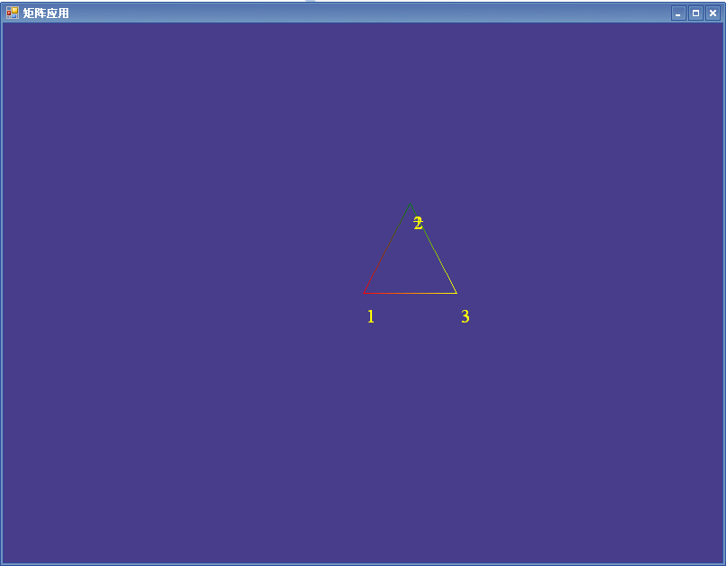
еҸідёҠеӣҫеҸҜи§ҒйҖҡиҝҮиҮӘе®ҡд№үз®—жі•дёҺDirectXдёӯжҸҗдҫӣзҡ„жҠ•еҪұз®—жі•еҫ—еҲ°зҡ„з»“жһңжңүе·®и·қпјҢе…·дҪ“е°ұжҳҜYж–№еҗ‘дҪҚзҪ®жңүе·®и·қпјҢиҝҷдё»иҰҒжҳҜз”ұWindowsзӘ—дҪ“зҡ„ж Үйўҳж ҸеҸҠиҫ№жЎҶе®ҪеәҰйҖ жҲҗзҡ„пјҢеҸҜд»Ҙе°ҶеүҚйқўжүҖжңүзҡ„д»Јз Ғthis.Widthжӣҙж”№дёәthis.ClientSize.WidthгҖҒе°Ҷthis.Heightжӣҙж”№дёәthis.ClientSize.HeightеҚіеҸҜи§ЈеҶігҖӮеҪ“然д№ҹеҸҜд»ҘеңЁMain()еҮҪж•°дёӯж·»еҠ еҰӮдёӢд»Јз ҒдҪҝеҫ—зӘ—дҪ“жІЎжңүжЎҶжһ¶пјҡ
MatrixExample.FormBorderStyle = FormBorderStyle.None;//и®ҫзҪ®зӘ—дҪ“ж— жЎҶжһ¶
иҝҗиЎҢзЁӢеәҸпјҢе…¶з»“жһңеҰӮдёӢеӣҫжүҖзӨәпјҡ
иҝҷж ·еҫ—еҲ°зҡ„з»“жһңе°ұдјҡжІЎжңүе·®и·қпјҢеҪ“然д№ҹеҸҜд»ҘеңЁзЁӢеәҸдёӯи®Ўз®—жҠ•еҪұеҲ°еұҸ幕дёҠYж–№еҗ‘ж—¶еҮҸеҺ»ж Үйўҳж Ҹзҡ„е®ҪеәҰжқҘе®һзҺ°гҖӮ
еҲҶдә«еҲ°пјҡ


зӣёе…іжҺЁиҚҗ
еҹәдәҺVisual C#зҡ„DirectXејҖеҸ‘е®һдҫӢпјҢж•ҷзЁӢпјҢзЁӢеәҸзӯүеӨ§е…Ё
ж–ҷзӯүпјҢдё»иҰҒд»Ӣз»ҚеҰӮдҪ•йҮҮз”ЁVisual C# иҜӯиЁҖеҜ№DirectXиҝӣиЎҢдёүз»ҙеӣҫеҪўејҖеҸ‘гҖӮжң¬ж–Ү е…ұеҲҶеҚҒе…ӯз« пјҢд»ҘвҖңз”ұжҳ“еҲ°йҡҫгҖҒз”ұз®ҖеҚ•еҲ°еӨҚжқӮвҖқдёәдё»зәҝпјҢд»Ҙд»Ӣз»ҚDirectX ејҖеҸ‘ж–№ жі•дёәдё»пјҢ并з©ҝжҸ’д»Ӣз»Қзӣёе…ізҡ„и®Ўз®—жңәдёүз»ҙеӣҫеҪўзҹҘиҜҶзӯүгҖӮ
жң¬ж–Үз»“еҗҲи®Ўз®—жңәдёүз»ҙеӣҫеҪўеӯҰе’ҢDirectXзҡ„ејҖеҸ‘её®еҠ©пјҢ并еҸӮиҖғеӣҪеҶ…еӨ–е…ідәҺDirectXејҖеҸ‘зҡ„д№ҰзұҚе’ҢзҪ‘з«ҷиө„ж–ҷзӯүпјҢдё»иҰҒд»Ӣз»ҚеҰӮдҪ•йҮҮз”ЁVisual C# иҜӯиЁҖеҜ№DirectXиҝӣиЎҢдёүз»ҙеӣҫеҪўејҖеҸ‘гҖӮжң¬ж–Үе…ұеҲҶеҚҒе…ӯз« пјҢд»ҘвҖңз”ұжҳ“еҲ°йҡҫгҖҒз”ұз®ҖеҚ•еҲ°еӨҚжқӮвҖқдёәдё»зәҝ...
Visual C#йЎ№зӣ®ејҖеҸ‘е®һдҫӢ иҮӘеӯҰжүӢеҶҢ,жҠҠд№Ұзҡ„жәҗд»Јз ҒдёҠдј иөҡз§ҜеҲҶ
Visual C# .NET зј–зЁӢз»Ҹе…ёвҖ”вҖ”д»ҺVB6еҲ°Visual C# .NET еҝ«йҖҹиҝӣйҳ¶
E:\Visual C#йЎ№зӣ®ејҖеҸ‘е®һдҫӢ\mr\ж–ҮжЎЈз®ЎзҗҶзі»з»ҹ.rar
гҖҠVisual C++йЎ№зӣ®ејҖеҸ‘жҢҮеҚ—вҖ”вҖ”е®ҡеҲ¶иҮӘе·ұзҡ„PhotoshopгҖӢ PDGж јејҸз”өеӯҗд№Ұе®Ңж•ҙзүҲ жң¬д№Ұд»Ҙе®һзҺ°вҖңжҲ‘зҡ„PhotoshopвҖқйЎ№зӣ®зҡ„ејҖеҸ‘иҝҮзЁӢиҙҜз©ҝе§Ӣз»ҲпјҢйҖҡиҝҮеӨ§йҮҸе®һдҫӢпјҢж·ұе…Ҙжө…еҮәең°д»Ӣз»ҚдәҶи®ёеӨҡVisual C++ 6.0зҡ„зј–зЁӢжҠҖжңҜеҸҠйЎ№зӣ®з®ЎзҗҶж–№жі•гҖӮжүҖи®І...
Visual C++ејҖеҸ‘GISзі»з»ҹвҖ”вҖ”ејҖеҸ‘е®һдҫӢеү–жһҗ
E:\Visual C#йЎ№зӣ®ејҖеҸ‘е®һдҫӢ\mr\дәәдәӢе·Ҙиө„з®ЎзҗҶзі»з»ҹ.rar
е®Ңе…ЁжүӢеҶҢVisual C# 2008ејҖеҸ‘жҠҖжңҜиҜҰи§Ј
Visual C#йЎ№зӣ®ејҖеҸ‘е®һдҫӢ дјҒдёҡе®ўжҲ·з®ЎзҗҶзі»з»ҹ.rar
Visual C#йЎ№зӣ®ејҖеҸ‘е®һдҫӢ\mr\зҪ‘дёҠиҙӯзү©е•ҶеҹҺ.rar
жң¬ж–Үз»“еҗҲи®Ўз®—жңәдёүз»ҙеӣҫ еҪўеӯҰе’Ң DirectX зҡ„ејҖеҸ‘её®еҠ©пјҢ并еҸӮиҖғеӣҪеҶ…еӨ–е…ідәҺ DirectX ејҖеҸ‘зҡ„д№ҰзұҚе’ҢзҪ‘з«ҷиө„ ж–ҷзӯүпјҢдё»иҰҒд»Ӣз»ҚеҰӮдҪ•йҮҮз”Ё Visual C# иҜӯиЁҖеҜ№ DirectX иҝӣиЎҢдёүз»ҙеӣҫеҪўејҖеҸ‘гҖӮжң¬ж–Ү е…ұеҲҶеҚҒе…ӯз« пјҢд»ҘвҖңз”ұжҳ“еҲ°йҡҫгҖҒз”ұз®ҖеҚ•еҲ°...
Visual C#йЎ№зӣ®ејҖеҸ‘е®һдҫӢ дјҒдёҡй—ЁжҲ·зҪ‘з«ҷ.rar
E:\Visual C#йЎ№зӣ®ејҖеҸ‘е®һдҫӢ\mr\иө„дә§иҜ„дј°з®ЎзҗҶзі»з»ҹ.rar
жҢәеҘҪзҡ„Visual_C#_2008вҖ”вҖ”и®ҫи®ЎQQз”ЁжҲ·зҷ»еҪ•з•ҢйқўVisual_C#_2008вҖ”вҖ”и®ҫи®ЎQQз”ЁжҲ·зҷ»еҪ•з•Ңйқў
第дёҖйғЁеҲҶжәҗз ҒвҖ”вҖ”дјҒдёҡе®ўжҲ·з®ЎзҗҶзі»з»ҹпјҢж•ҙдёӘйЎ№зӣ®зҡ„жәҗд»Јз ҒйғҪеңЁиҝҷйҮҢгҖӮ
Visual C#йЎ№зӣ®ејҖеҸ‘е®һдҫӢ иҮӘеӯҰжүӢеҶҢ дёҠдј иөҡз§ҜеҲҶ
гҖҠVisual C++ејҖеҸ‘GISзі»з»ҹвҖ”вҖ”ејҖеҸ‘е®һдҫӢеү–жһҗгҖӢйҷ„д№Ұжәҗд»Јз Ғ.zip